This is my first post in my exploration of ParaView’s raytracing functionality and will focus on the scivis component. Scivis is targeted not on full photorealism but rather a halfway towards photorealism while still presenting scientific data. In this case I have a sample data set from an OpenFOAM CFD run of the classic dam break laboratory experiment. The free surface was extracted from OpenFOAM using the Catalyst plugin and there is a simple STL shape to represent a cut out of the container that held the water. To add to the visualisation I’ve added a VTK plane object to represent the floor of the laboratory where the “experiment” would run.
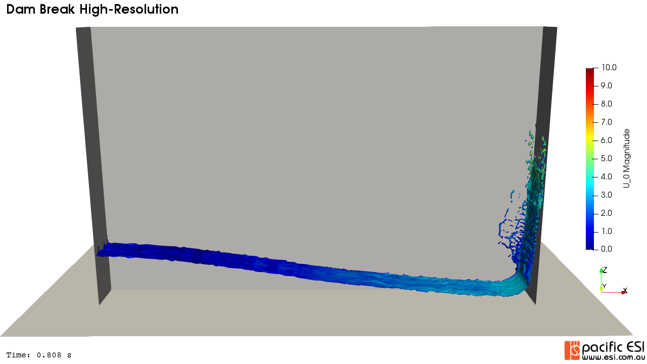
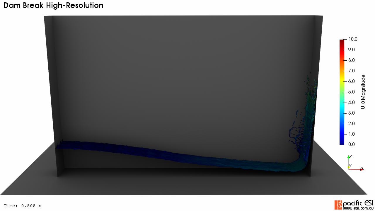
My starting point, as always, is a base render view in ParaView using the native tools, as shown in Figure 1. Something like this is usually pretty quick and easy to set up and is actually what most of my clients want 90% of the time. For the rest, we have raytracing.
My aims for this project are to make this feel more “real” yet still convey the speeds the free surface is moving. To achieve that I think I need:
- Shadow effects to give the impression of lighting and depth
- “sparkle” on the free surface as if light were reflecting off the ripples
- Some depth shading on the container and floor would also be good.
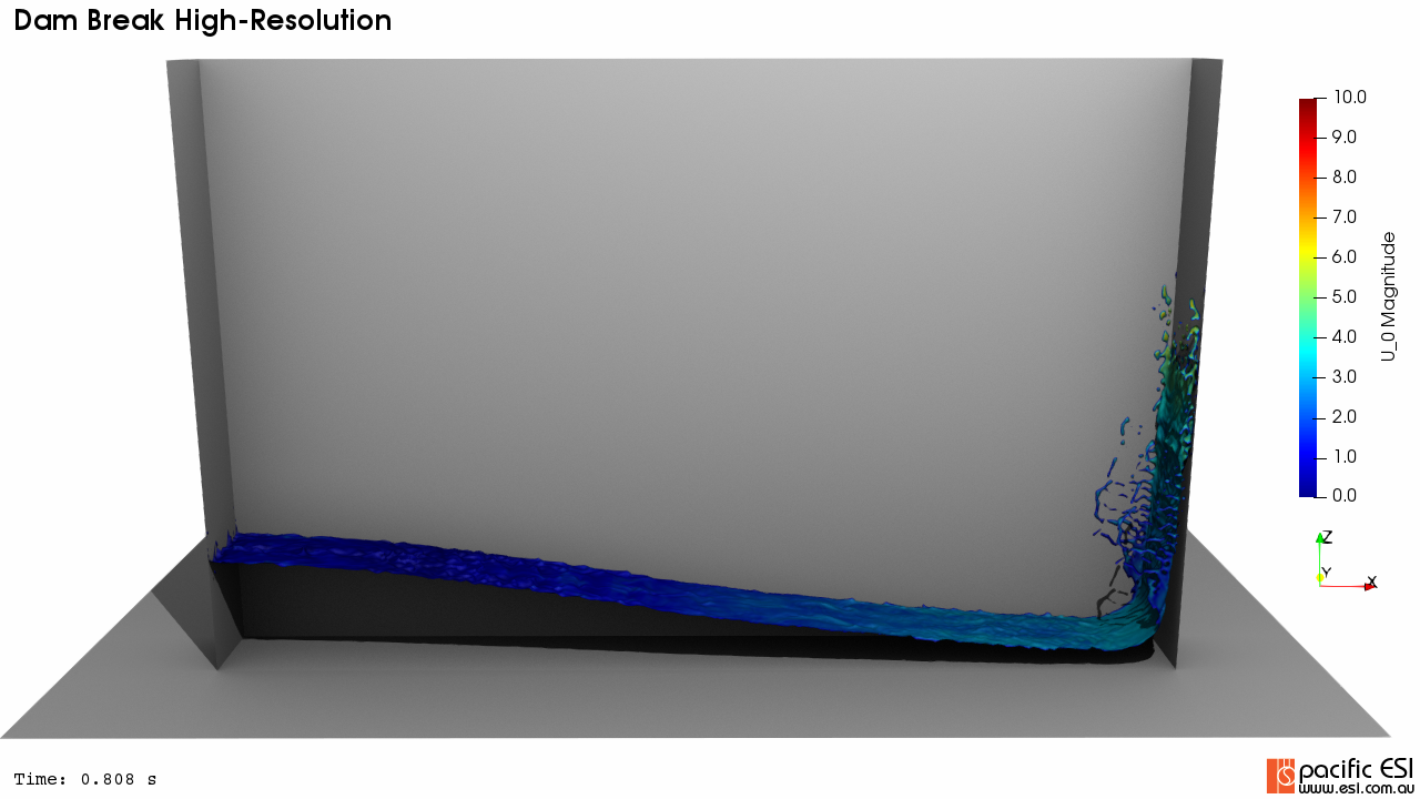
The first step is simply to turn scivis on and add shadows. ParaView by default sets up a four-point lighting rig for us that it refers to as “Light Kit”. The default render result is, to say the least, not that great, as shown in Figure 2.
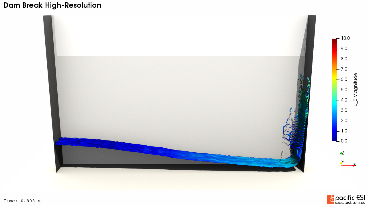
Now, Light Kit is a great start and I leave it on to begin. It is very quick, covers a lot of circumstances and certainly lets me set the basic material properties that I want. For example, in Figure 2 my containment box looks strange and the base floor plane that I added is essentially gone. Let’s add those back in and improve their appearance first.
My first step here is usually always to lower default diffusivity from 1 to 0.8, say. From the VTK User Guide the three parameters:
- Diffuse coefficient
- Ambient coefficient
- Specular coefficient
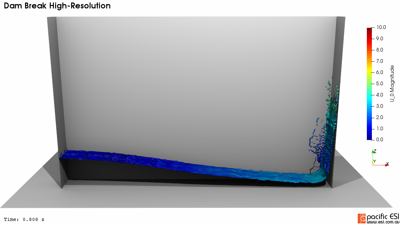
Would usually be expected to sum to 1. I find that starting at diffuse = 0.8 and specular = 0.2 is a good first attempt, as shown in Figure 3.
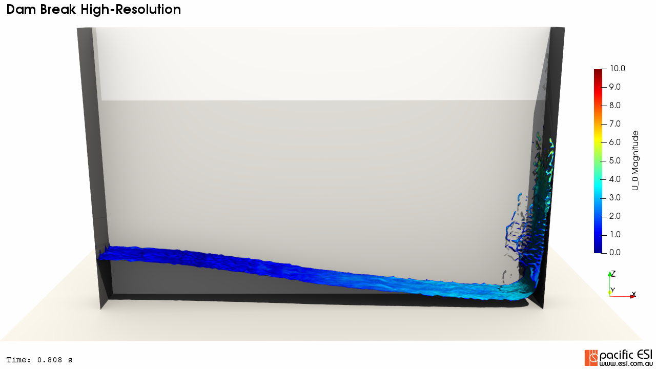
Immediately this has improved as the base plane is back and the containment box looks better in the corners and shadows.
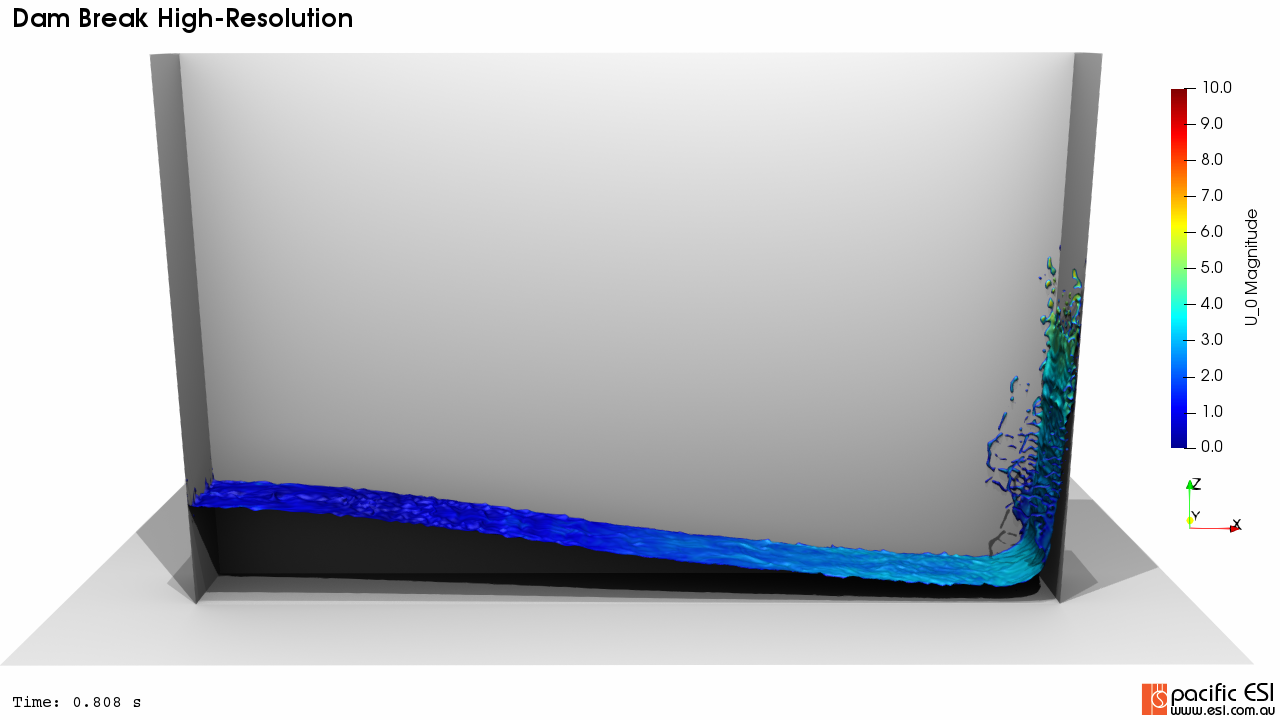
Next, as I’m rendering fluid flow I like the free-surface to have a bit of reflection and shininess, as if you were seeing sunlight reflected off ripples in a river. To do that I’m going to add back specular highlights and power. This is an iterative process as it changes with the angle of the surfaces and lighting.
Next, as I’m rendering fluid flow I like the free-surface to have a bit of reflection and shininess, as if you were seeing sunlight reflected off ripples in a river. To do that I’m going to add back specular highlights and power. This is an iterative process as it changes with the angle of the surfaces and lighting.
Please note that with specular reflection on coloured surfaces some detail relative to the reference colour bar will be lost. It’s a trade-off between pretty verses scientifically accurate. My personal preference is for only slight highlights to illustrate waves and other surface anomalies yet still remain close to the colour scale, as shown in Figure 4.
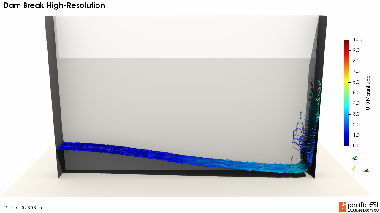
Honestly, we could actually stop here, hit run on the render and come back. It looks pretty good really. My major complaint would be that the shadow lines on the right-hand wall are quite deep and I’m losing some definition in that corner. Beyond that, the weird looking shadow three quarters of the way up the back face of my container is not really what I want, rather I want the viewer to focus on the free surface.
There are really two choices on proceeding from here:
- Leave the default Light Kit on and add additional lights to balance
- Turn off light kit and start to add your own light sets.
My preference is to go with option 2 and treat this exactly like it is a physical experiment that I’m lighting: I’ll set up one light source at a time and move logically through the scene. In this case I’m after similar to what I’ve done in the lab: I want two lights slightly above and looking down to illuminate the free-surface and into the corners. I’m not fussed with shadows down the back along the floor plane as I want the focus to be on the surface deformations.
When doing this I use the custom view port function extensively. I set viewport 1 to the be the camera location and then move back and forward setting the lights. From there, step 1 is to turn off Light Kit to get a baseline dark scene, as shown in Figure 5, and then add the lights you want from there sequentially until you are happy with the scene.
The first light I added was up and to the right of the viewpoint, as shown in Figure 6. The scene is quite dark but I’m not concerned about darkness right now – remember it will become brighter as we add more lights. I am really interested in the shadow paths now: specifically into the corners of the containment box.
Next, I’ve added the light on the left and up, as shown in Figure 7. Again, I’m focussing on the shadow lines and the direction the new light is coming in from but immediately you can see that whole scene is brighter.
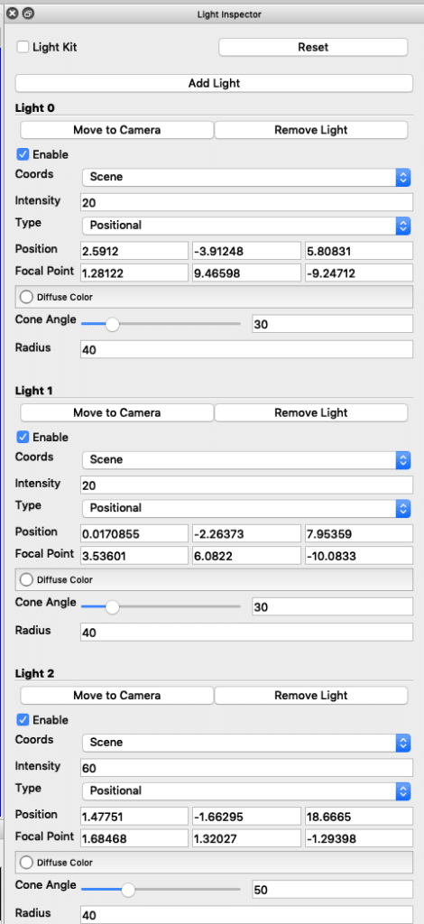
Finally, I think that the free-surface is still a little dark so I’ve added one more light, as shown in Figure 8. This light is quite powerful but is a relatively large distance from the container and is quite high looking directly down.
I’m pretty happy about this really. The shadows are quite deep below the water but the splash highlights on the right jump out. There are a few small specular highlights from free-surface but there is still good colour definition relative to the colour scale. Finally, the shape and outline of the container is well defined with no mid-height shadow lines to distract from the free-surface. The final lighting rig is shown in Figure 9.
Time to push this off to my render cluster at the Pacific ESI office, go out for a break and see the results. The final details to know are that for the final run I used 10 ambient occlusion passes and 1000 rays per pixel on a 1280×720 frame. When testing I leave these down at five and five, respectively. ParaView does have an idiosyncrasy though in that when changing values it does not always trigger a re-render – I suspect that this is because I’m using a Mac client front end, connected to a headless OMesa render cluster. In these cases, I’ve just become accustomed to push up and down a frame to force a re-render. This cheat works for this data set as its relatively small to load a VTK surface object but could rapidly become painful for a larger data set.
The full render is below.
Finally, thanks for reading this article and please leave a comment below. If you are interested in being updated when similar items are posted then either subscribe via RSS or sign up to my mailing list below.

