Working with some collaborators at the University of New South Wales and UTS recently I was struck, yet again, with the need to properly understand the physics of what you are attempting before starting at the CFD solver. In this work we were using CFD-ACE+ from ESI.
PS: this article is a cross post from something similar I posted on the Pacific ESI site and LinkedIn.
Problem Description
The problem that we were interested in is surprisingly simple yet generates very complex flow fields. Imagine a vertical chimney, except we are not injecting heat at the base of the stack with a fire but have some thin film heaters on the side walls. There is some vertical insulation that the heaters are mounted on and two fairing plates, one at the lower throat of the chimney and one at the top outlet. Above the top is a splitter plate as shown in Figure 1 below.
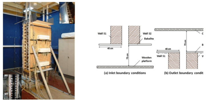
The splitter plates are built from Bakelite with an expanded foam insulation and the wood supporting structures were not simulated. We assumed standard physical properties for the Bakelite and foam, as listed in Table 1.
| Property | Bakelite | Foam |
| ρ | 1300 | 960 |
| Cp | 920 | 1300 |
| k | 0.2 | 0.033 |
The air within the domain was assumed to be standard compressible air with properties that varied as a function of temperature.
Attempt 1: Naïve Approach
I became involved after the first attempt was a pretty dismal failure: simply simulating the chimney and heating elements resulted in an almost laminar flow that did not compare with the experimental results, as shown in Figure 2a. Clearly, we’d got the physics wrong here as we were not simulating either the foam insulation or the inlet and outlets into the room. Unfortunately, this is a common CFD problem: mathematically our BCs worked as desired, physically our assumptions were incorrect.
Attempt 2: Extend to Partial Room
The next attempt at simulation was to extend the inlet and outlet boundaries more into the “room”, as shown in Figure 2b. This was much more interesting as we observed the unsteady wall bursts that we expected but there was way too much heat being injected into the channel – we’d failed to consider the energy that was being injected into the insulation and subtracted from the main stack. We are improving from here.
Attempt 3: Partial Room Plus Insulation Blocks
Finally, we arrived at a simulation that seemed to correlate with our physical experiments, as shown in Figure 2c. The significant conclusion for us is that we had assumed that as the insulators were installed to contain the energy within the main channel that we could ignore their effects on the flow field. Turns out that we were quite wrong in that regard and that during the start-up phase of the experiment a significant block of our energy was being sucked into the insulation. Second, the shape of the inlet throat does seem to encourage early separation as the air is drawn into the channel.
Looking at the progression in Figure 2 between our three attempts did prompt a question: if we are seeing such a dramatic change in the flow conditions by pushing the boundaries out through what is relatively small changes, what effect does the room have?
Attempt 4: The Full Room (Well in 2D at least)
Therefore, the only way to answer if the room effects to the flow was to run the simulation, which we did as shown below in Figure 3. Bear with me here – it’s a long video but there is a lot of physics involved that get very interesting towards the end. And I’ve already increased the framerate from real time to get a better understanding.
A number of really cool features jump out for me right away:
- During the initial impulse start it appears as if the outlet of the chimney chokes as the wall drive flumes interact near the exit.
- The two semi-symmetric vortices generated from the left- and right-hand side heat plumes are very interesting.
- After which the plumes merge and form almost the classic image of a laminar to turbulent plume transition before the plume impinges on the splitter plate.
- While the plume and the plate interaction are engrossing to watch at this stage the main room is a little boring as it is starting to stratify.
- By 100 s of simulation time you can see that the outer walls are starting to drive flows in the room – in this simulation the walls were adiabatic so the downward flows are momentum driven rather than temperature driven.
- Starting at around 150 s the first downward driven plume interacts with the chimney throat and there is a change in the boundary layer on the right-hand side of the inlet. It grows and then shrinks again as if a wave is passing through: so the room is important to the chimney!
- As the simulation progresses, around the 300 s mark, there are distinct downward plumes being driven in the near chimney region due to the colder outside faces of the insulation blocks.
- By 330 s the room is sufficiently stratified that warmer regions are regularly being ingested into the chimney and the effects are huge. For a +1 °C change, there are large fluctuations in the performance of the chimney with resultant capture of the flows within the chimney leading to a hotter internal structure.
- By 700 s to 800 s the room is significantly stratified and warm air is being continuously ingested by the chimney. In this form the points discussed above in 8 are being amplified.
Other than number crunching time, there was a bit of work taken to get to this point. The key being that we had to actually simulate an air gap representative of that under a door to balance out the pressures. Reflecting this should be obvious: if you inject heat into a closed container the pressure will rise. As this clearly did not happen in the physical experiments, we must also account for that in our simulations. Hence, we accounted for that with an air gap low on the left-hand side, as shown below in Figure 4.
Conclusion
This was a fun project to work on but really reinforced to me, again, a few things:
- Try to really understand the physics of your flow problem to design your simulations: get your boundary conditions right!
- Don’t be afraid to fail and try again – in fact assume that your initial simulations will not work out as you desire but learn from them and improve
- Enjoy the animations once you get it going.
Beyond these, there is a lot of physics going on here. UNSW is continuing the work now to break down what is going on to use the results to feed back into their experimental and numerical programmes.
Finally, thanks for reading this article and please leave a comment below. If you are interested in being updated when similar items are posted then either subscribe via RSS or sign up to my mailing list below.

